How to Draw a Spring in Autocad 2000
Instructions:
Take notes on the following information. At the bottom of this screen is a link to a practice quiz based on the information given on this page. Compete the practice quiz and take note of the questions you missed. Write down each one you missed. Question and answer. (x5)
DRAWING AN OBJECT IN AUTOCAD
Once AutoCAD is installed. Open a blank drawing file and let's start playing.
TWO SIMPLE STEPS
1 – Click on the white sheet on the left upper corner
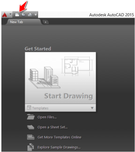
2 – Click on Open
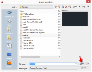
You are now in the main window. Feel free to close the window on the left side (if you are working on the same version as I do), it wont be useful for now.
If you did close the left windows, the following image is what you should be left with.
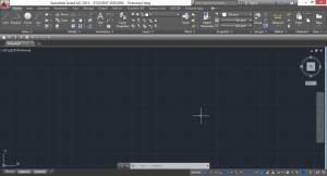
We are now set to start running.
DRAWING A LINE IN AUTOCAD.
Not to go to fast, we are going to draw a line.
Google says that in analytic geometry, a line in the plane is often defined as the set of points whose coordinates satisfy a given linear equation, but do not worry! we are not going to start talking about equation and algebra here, I would like to deteriorate that definition a little to make it more simple for us.
We will define a line here like a straight rope that need two points to hang itself on.
How will this definition help us here? It will help us remember that AutoCAD need information about the location of the two points to be able to draw a line, provided the fact that the line command is activated.
A LINE
To draw a line in AutoCAD. follow the following.
1 – Activate the LINE command with a click on its appropriate icon.
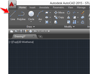
2 – Click anywhere in the drawing area to tell AutoCAD where you want the first point to be
3 – Repeat the previous step after sliding the cursor away from the first point.
4 – Press the ESC key on your keyboard to Cancel the command.
If you have more than a line to draw, you don't have to start each by starting all over again. You might have noticed that after step 3, AutoCAD was letting you draw another line considering its beginning was at the end of the previously drawn line.
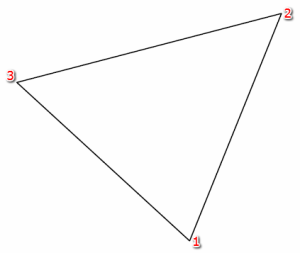
If you look at the object below, you will see that it has 3 points.
If we were to draw this (we do not care about dimensions and line inclinations for now), we will
- Activate the Line command
- Click to indicate the point 1
- Click to indicate the point 2
- Click to indicate the point 3
- Click on point 1 again to close it
- Press the ESC key
You must still have many questions about drawing a line, No worries! More will be covered in next tutorials. Possibilities might still remain few with what you know so far. As you learn possibilities will increase.
The Environment
AutoCAD has gone through major redesigns since its first release in 1982, but its core functionality has remained unchanged.
Depending on the version of AutoCAD you are using, you will find similarities with the version used in the upcoming images.
The following images we will learn about the AutoCAD environment. Be sure to take note of the proper object and its proper vocabulary meaning.
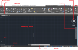
THE DRAWING AREA
The drawing are in AutoCAD is made of a universe of points where each has x, y and z coordinates. You can actually draw using the coordinate system. For a line you can define exactly what point on the drawing area your starting point and your ending point are going to be.
For a 2D design, we will ignore the value of z in the coordinate.
EXAMPLE
Draw a triangle with its corners at each of the following point: A(254,362) B(632,364) C(246,666). How do you go about this in AutoCAD?
What you do is the following.
First understand that A(254,362) means that the point A has its x coordinate at 254 and its y coordinate in 362. A(x,y)
Make sure the dynamic input is not activated.
Make the Dynamic Input icon available on the Status Bar
It will appear on your Status bar, Turn it OFF
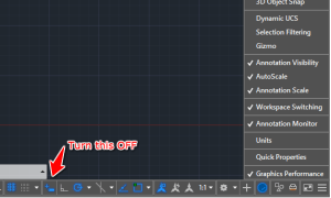
Now, what you do is:
- Type LINE and hit ENTER
- Type 254,362 and hit ENTER on your keyboard
- Type 632,364 and hit ENTER on your keyboard
- Type 246,666 and hit ENTER on your keyboard
- do step 2
- Hit ESC
You should end up with the following image.
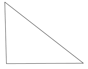
For the most part, we will deal with 2D objects, meaning the USC icon will almost always look like it is on the first image above. (without the z component)
THE DRAWING AREA
It is possible to change the background color of your drawing Area.
To change the color and the look of the drawing Area
1 – Right click in the drawing Area and click on Options
2 – On the Display tab, Click on the Colors icon

The following window gives you the ability to customize the visual aspect of AutoCAD

Much can be customized in AutoCAD.
DRAWING A LINE WITH A DIMENSION IN AUTOCAD
We need to talk about the ORTHO mode before anything else here.
THE ORTHO MODE
The ORTHO mode constrains the cursor to horizontal and vertical movement, which helps you draw straight horizontal and straight vertical line easily.
Every time I need to draw an either vertical or horizontal straight line, I will make sure the ORTHO mode is activated.
The ORTHO icon is located in the Status Bar
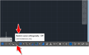
HOW DO YOU KNOW IT IS ACTIVATED OR NOT?
Pay attention to the information box that pops up when you hover on the icon. You can also use colors to know, Blue ORTHOMODE icon for ON and White ORTHOMODE icon for OFF.
HOW DO YOU ACTIVATE THE ORTHO MODE?
Just click on the icon to toggle it. If it was OFF before your click, it would turn ON and vise versa
Now that we know what ORTHO is and how to operate it, we need to make use of it.
VERTICAL LINE OF 50 UNITS OF LENGTH.
To draw a line with 50 units:
1 – Click on the LINE icon

2 – Click one time in the drawing area (Don't hold your click)
3 – Activate the ORTHO mode if it is not activated
4 – Move the cursor away from the first point in the direction your want the line to have. Since we are drawing a vertical line, you can only go either upward or downward
5 – Type 50 on your keyboard and hit ENTER
To draw an horizontal line, just change the direction in step 4 to either left or right.
PRACTICE EXERCISE
Using what you have just learned, you must be able to complete the following exercise.

I don't expect you to be able to draw the figure with dimensions, it is only there for information purpose.
POLAR TRACKING
This feature helps track specific angles when you are drawing in AutoCAD. By default this is set to90, 180, 270, 360.
HOW TO ACCESS THIS?
Right click on the Polar tracking icon like shown on the image below
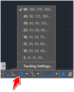
WHAT CAN I USE THIS FOR?
You can use it to draw the following 2D image.
HOW DID WE GET THESE?
Remember earlier in this article when we used ORTHO? We were only able to draw vertical and horizontal lines, now we can also track direction with specific angles. The process is the same with what we did when drawing the square above, but now we need to set the polar tracking to45, 90, 135, 180… , draw the base line as we did with the square, and use the polar tracking to know you are at 45 degrees before drawing the 90 unit line.
You can set these tracking angles to be whatever you want. Using the Tracking settings, you can enter your angle of preference.
Now, we must learn a little about trigonometry before moving forward.
The concept of polar coordinates in AutoCAD obeys the principle of the trigonometric circle, thus creating the need to revise that part of math for a minute.
TRIGONOMETRIC CIRCLE
The trigonometric circle goes from 0 degrees to 360 degrees. One lap of the circle is 360 and 360 degree on is equivalent to zero degree on the circle.
Here is what the circle looks like
The mastery of the concept of angles is crucial to your ability do get things done in AutoCAD. You have to be capable of quickly deducting what the value of an angle is from zero.
On the images above you will notice the trigonometric circle with angles counted respectively from the positive side (anticlockwise) and from the negative side (clockwise)
Notice -90 degrees = 270 degrees, 22.5 degrees = -337.5 degrees… and all other similarities
One of the most important information to have in mind is that AutoCAD always start counting angle from zero. You will see why remembering this is important when you read further below.
ANGLES AND LINES IN AUTOCAD
To draw a line in AutoCAD you can use the command line length<Angle.
EXAMPLE 1
To draw the line of 150 units, you will have to
- Activate the LINE command
- Click in the drawing Area to specify the start point
- Type 150<30 and Hit ENTER
- Press ESC
where 150 is the length of the line and 30 is the angle the line makes with zero.
If I had written 150<-330 at step 2, it will give the same result.
EXAMPLE 2
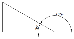
What if the figure were disposed like this? How would you draw that 150 units line?

To draw the line of 150 units, you will have to
- Activate the LINE command
- Click in the drawing Area to specify the start point
- Type 150<150 and Hit ENTER
- Press ESC
where the first 150 is the length and the second 150 is the angle. Why 150 for Angle? Because AutoCAD count angle from the zero angle, So to find the angle from zero, we needed to do 180-30=150.
EXAMPLE 3
How about the following case
To draw the line of 150 units, you will have to
- Activate the LINE command
- Click in the drawing Area to specify the start point
- Type 150<210 and Hit ENTER
- Press ESC
To find 220 we made 180+30.
Remember the flat angle is 180 degrees and we AutoCAD counts from zero.
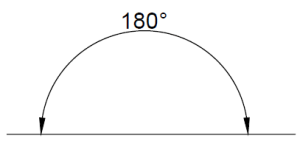
EXAMPLE 4
And this case
To draw the line of 150 units, you will have to
- Activate the LINE command
- Click in the drawing Area to specify the start point
- Type 150<-30 and Hit ENTER
- Press ESC
FINAL WORDS
You should now be able to know what information to give AutoCAD if you happen to deal with projects where angles does not have the zero angle as reference.
Here we are working with the 2015 version of AutoCAD.
BEST SETTINGS IN AUTOCAD
DYNAMIC INPUT
We have seen in AutoCAD tutorial 02 how to disable and enable the Dynamic input. You need to be able to have it displayed in your Status bar because you will need to turn it ON and OFF quite frequently.
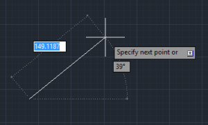
Dynamic input displays options, commands and user input in a tooltip near the cursor when you are drawing.
DYNAMIC INPUT ENABLED
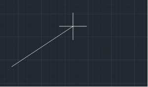
DYNAMIC INPUT DISABLED
OBJECT SNAP (OSNAP)
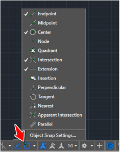
OSNAP is a tool that ensures precision while drawing. You use this to help you grab points on existing objects.
Options that are important to us right now are: Midpoint, Quadrant and Tangent. You need to activate them on the list. ( Right click on the OSNAP icon to have the list displayed like on the image above)
MIDPOINT
Midpoint will help you achieve figures similar to the following.

To draw the segment BA, we needed to know exactly where the middle of DE was. whenMidpoint is activated, we just have to hover the cursor close to the center of DE after activating the LINE command for AutoCAD to help us snap the start-point at the center of DE.

Notice the Green triangle indicating the middle of the line.
QUADRANT
Quadrant will be essential while working on the following example. You need to be able to hook A, B, C and D on right points.
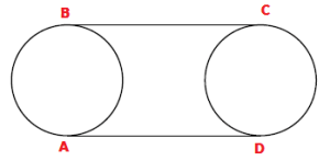
TANGENT
Tangent will be useful if you have the following to draw.

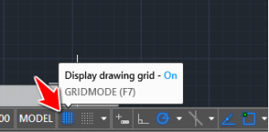
GRID
Just for the sake of knowing, Grid displays a series of graph paper style lines that can serve as distance of reference.
UNIT
You should know that at the beginning of every project, you need to set the unit in which you will be drawing. To access it, simply
- Type UNITS
- Hit ENTER
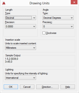
You can use the LENGTH section to set the format for units of measure. For example if you choose Engineering and Architectural formats, AutoCAD will assume that each unit represents one inch.
You can as well set the Angle format.
Insertion scale helps control the unit of measurement for blocks that are inserted into you drawing. It is recommended to select Unitless to be able to insert blocks without scaling them to match the specified units.
PROCEED HERE FOR THE OVERVIEW ASSESSMENT. NOTIFY INSTRUCTOR BEFORE YOU BEGIN
campbellformiscrad.blogspot.com
Source: http://designbuildacademy.com/spring-refresh-autocad-basics/
0 Response to "How to Draw a Spring in Autocad 2000"
Postar um comentário